Quality control (QC) is an important aspect of any manufacturing process, as it is essential to guarantee you get what you requested.
To control the quality of your products there are different things you need to do. Among them, ensuring physical and geometrical characteristics match the requirements of the design from prototyping to the final product. And here is where the Coordinate Measuring Machine, also known as CMM, stands out.
What is a Coordinate Measuring Machine?
A Coordinate Measuring Machine consists of three main parts, and it is used to measure the physical and geometrical characteristics of parts along the production process to guarantee the fulfillment of the product specifications. It is called coordinate because it uses a coordinate system on three axes (X, Y, Z). The main parts are:
Base
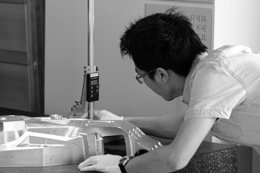
As in many machines where the part is going to be processed, the base is used to place the part on a stable surface, usually being a heavy granite slab or any other material which is not affected by changes in the environment with a totally flat surface to ensure the quality of the measures taken.
Mobile Table
The base is fixed, but a mobile table is mounted on the base. The movement of this table defines the X-axis for the coordinate system, so it is said that the mobile table moves along that axis.
Measuring Probe
The measuring probe is usually installed on a vertical position by means of a vertical shaft. A horizontal beam, supported by vertical posts that are normally part of the machine frame, keeps the shaft in position and allows its movement along the Y-axis.
On the other hand, the shaft can move vertically, thus defining the Z-axis of the coordinate system of the machine.
How are the measurements taken on a CMM?
As mentioned before, the machine has a defined coordinate system. It uses this system to identify unique points on the part being measured by moving the probe on the Y and Z axes, while the mobile table moves the part on the X-axis.
When the probe identifies these points, the information is sent to the machine’s software which calculates distances between points, or any other required measurement such as surface flatness and profile, roundness, symmetry, angularity, among others. The result is an image that represents all the information in something like a 3D map to facilitate visual understanding of the data.
Who should use this technology?
We have established quality control is essential for any manufacturer. Moreover, knowing the geometrical characteristics of a part or product permits us to compare them to the product specifications that have been approved. Therefore, first article and first piece evaluation and critical dimensional profile measurements are possible. The result of this practice is a beneficial reduction in costs derived from rework and shipment delays, as it is possible to determine whether the product specifications are met even before production or shipment.
In other words, any manufacturer trying to meet very demanding requirements and tight tolerances can benefit from using a CMM.
It does not always make sense to use a CMM though, as there are many parts and dimensions which can be measured quicker and with as much accuracy using other equipment.
If you are not sure about using one for your specific application, you can discuss your projects QC requirements with one of our projects team
HLH, we make things for you
info@hlhprototypes.com